
CONTENTS
What changed with §14a EnWG? Key implications for OEMs
How EEBUS, SPINE, and SHIP protocols support §14a readiness
§14a readiness is a market-access investment, not just a one-country retrofit
Thank you for reaching out to Sigma Software!
Please fill the form below. Our team will contact you shortly.
Sigma Software has offices in multiple locations in Europe, Northern America, Asia, and Latin America.

USA

Sweden

Germany

Canada

Israel

Singapore

UAE

Australia

Austria

Ukraine

Poland

Argentina

Brazil

Bulgaria

Colombia

Czech Republic

Mexico

Portugal

Romania

Uzbekistan
12 min read
OEMs operating in Germany often interpret §14a readiness as the ability to receive grid-control signals. Yet, the compliance scope goes deeper, creating a new control logic for remotely governing the product’s behavior. §14a carries extra implications for the device’s firmware, security model, and failure-handling methods. This post breaks down the main implications of §14a EnWG for OEMs and explains how the EEBUS protocol suite supports the transition.
What changed with §14a EnWG? Key implications for OEMs
How EEBUS, SPINE, and SHIP protocols support §14a readiness
§14a readiness is a market-access investment, not just a one-country retrofit
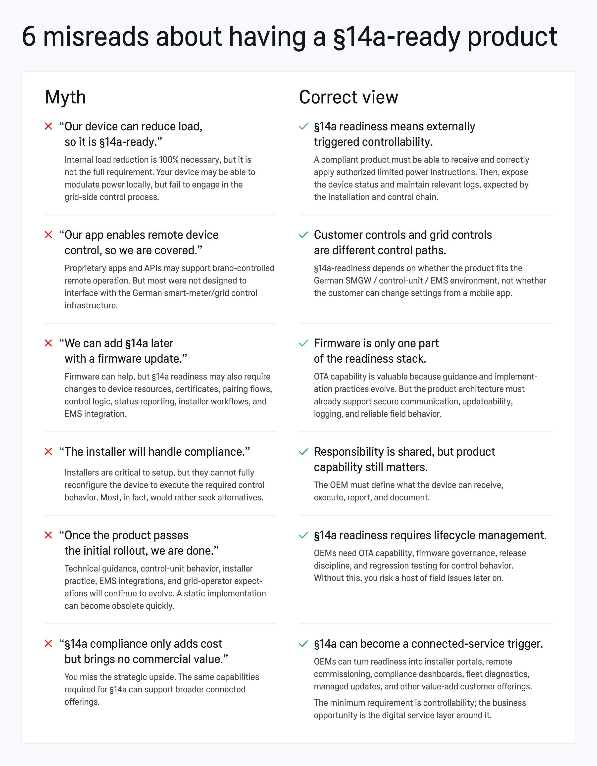
It’s a big day at your office — you’ve just signed a new client in Germany to install a hefty number of your EV charges. The product can reduce load on demand, and the customer app is polished. All looks tidy, so your product team is ready to take the victory lap.
But…one last email arrives, asking for more §14a controllability evidence for the device. Suddenly, the confetti starts looking premature.
A cursory scan of §14a EnWG leads many teams to assume that load reduction is the only requirement. In fact, §14a readiness depends on whether the device can participate in a specific life cycle sequence required by the German grid-side control chain.
Effectively, Germany has turned device controllability into a market-access requirement for connected appliances above the relevant power threshold, including EV chargers, heat pumps, air-conditioning systems, and battery storage systems, among others.
This post breaks down all the implications and shows what it takes to demonstrate §14a readiness for your product.
On 1 January 2024, Germany implemented extra controllability requirements for consumption devices (aka steuerbare Verbrauchseinrichtungen or SteuVE, for short).
All devices with a network connection power above 4.2 kW, like private EV charging points, heat pumps, air-conditioning systems, or electricity storage systems, must be able to reduce grid draw when the local network is at risk of overload, based on instructions from the network operator.
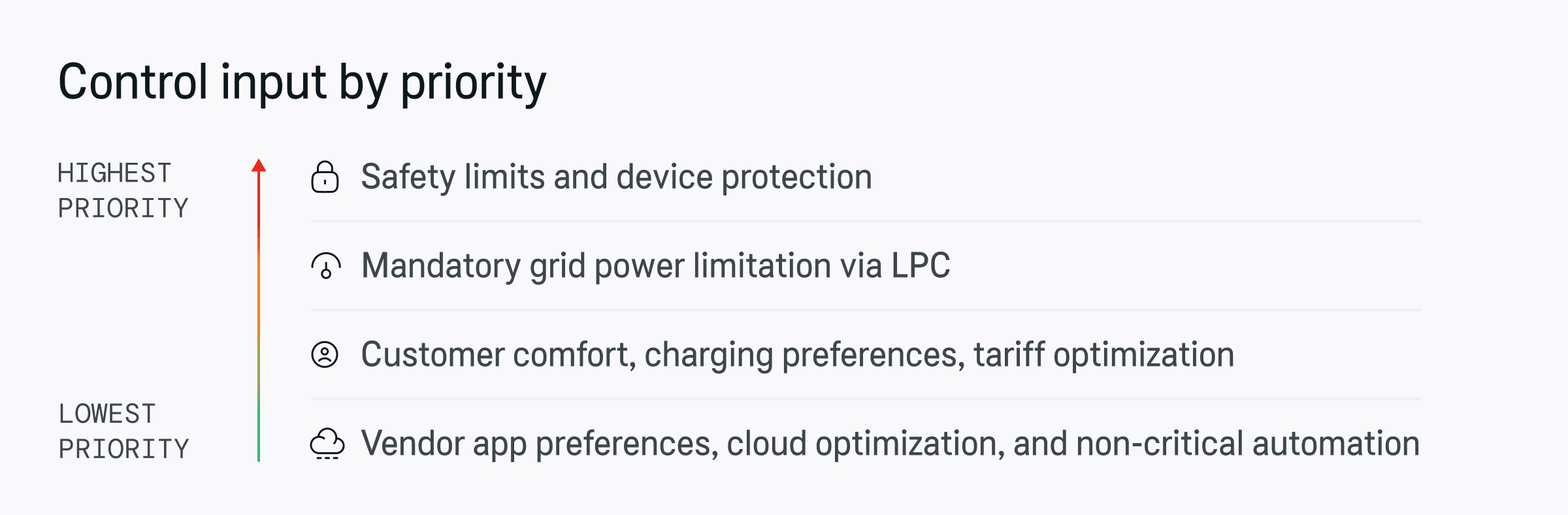
In simple terms, §14a establishes the requirement to support Limitation of Power Consumption (LPC), with a caveat that all concerned devices must be controllable regardless of whether the DSO actually issues limitations or not.
This carries a major implication for OEMs:
For instance, EV charger §14a compliance means that the wallbox must be able to receive a control system from the German smart meter gateway CLS, interpret it correctly, apply the limitation, maintain safe operation, expose its status, and recover cleanly after a temporary power interruption.
This is where the scope readiness starts to widen. Once controllability becomes a market-access requirement, interoperability, firmware governance, and service operations all move closer to the center of the product roadmap.
§14a readiness requires new control paths. In the German model, the signal may move through the smart-metering and control environment: grid-side process, metering-point operator, smart meter gateway, control unit, CLS communication environment, local interface, EMS / HEMS, and finally the controllable device. The exact architecture can vary, but the product has to slot into either option regardless.
So, interoperability becomes non-negotiable. The product roadmap now has to consider integration with:
In many cases, existing apps may not be cut because most are focused on brand-controlled device management. Whereas Germany requires explicit participation in an authorized grid-side control process. Your device has to be configured to specifically support interactions with the German control chain, rather than support some general controllable logic.
Your device may still include additional on-device controllability to support customization, local automation, and other customer experience interactions. However, existing controls may not be enough to signal §14a readiness, unless they were tested against the German implementation context.
Like other regulations, §14a issues high-level requirements. In practice, technical recommendations, control-unit behavior, EMS integration patterns, and general market practices are open to interpretation and thus keep evolving.
VDE FNN, the German technical regulator for power grids, issued recommendations for using EEBUS or KNIX as shared communication standards in the grid control process.
In both cases, OEMs may choose different implementation approaches. For example, use direct device control, EMS-mediated control, or gateway-based protocol translation. The underlying data model in EEBUS is standardized, but OEMs still need to map LPC commands into their own firmware logic, which can add real pressure to the firmware strategy.
Depending on the market direction and client requirements, OEMs may need to update:
Without a reliable OTA capability, every change to controllable logic becomes both slow and expensive. For a heat pump manufacturer with thousands of installed units, a field update problem can quickly become a retrofit, warranty, and channel-support problem.
Delayed action can also undermine your connected product strategy. If you plan to transition from hardware-centric products toward IoT-enabled digital offerings, a lack of interoperability can become a significant blocker. On the pro side, working towards §14a readiness makes connected-product capability part of compliance execution.
Many OEMs see §14a readiness solely as a compliance requirement. But §14a can become a trigger for building a connected service layer.
OEMs can use the same capabilities required for readiness — connectivity, secure firmware updates, device status, commissioning data, diagnostics, or fleet visibility — to create value-added connected services, like:
A heat pump manufacturer, for example, could treat §14a as the minimum bar: the device can accept external limitations and report status. Yet, the same architecture can also support predictive maintenance, installer support, customer energy optimization, and managed updates. That moves the product from a one-time hardware sale toward a more profitable connected service model.
A remotely controllable energy device is not the same as a connected appliance. Because it participates in a security-sensitive environment, it needs to have appropriate security safeguards for:
Current best practices specifically point to functional and IT security requirements for the control interface and documentation obligations. Operators and manufacturers are also required to ensure and prove that control commands are successful.
In other words, a product that can dim consumption but cannot generate reliable evidence of what happened is not truly ready for the German operating model. So you have to also consider broader connected-product security requirements like proper vulnerability handling and NIS2-readiness.
Naturally, the next question is: how do I get my product §14a-ready?
The short answer is: You’ll have to implement extra communication capabilities to exchange data with all the German grid participants.
EEBUS is currently the industry-favored format for standardized communication between energy devices, energy management systems, and grid-side infrastructure. It’s been endorsed by local regulators and successfully trialed by several OEMs, including NIBE, Bosch, Vaillant Group, and SMA Solar Technology AG, among others.
Within EEBUS, there are two key layers: SPINE and SHIP:
In practice, an EEBUS-based execution sequence for limiting power consumption on a device goes like this:
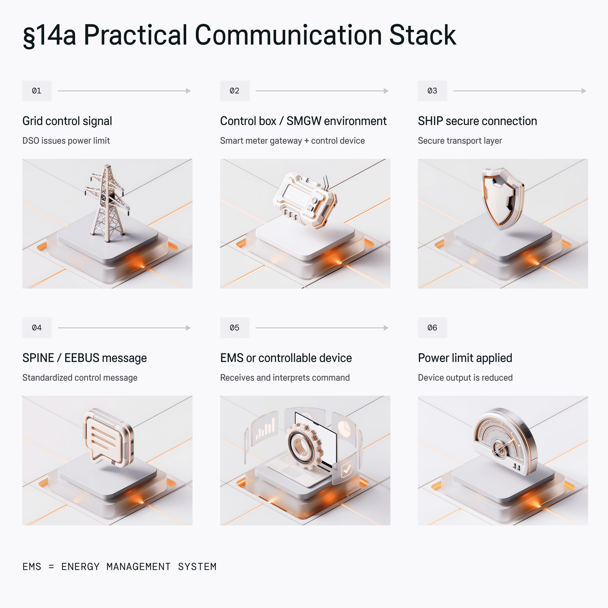
Let’s take a home energy management system §14a readiness scenario to illustrate the above.
An EEBUS limitation of power consumption (LPC) implementation allows a grid-facing controller to send a maximum active-power consumption limit to a controllable system — the HEMS.
Let’s say the grid authority detects congestion in your sector. An EMS then receives a limit request, which is sent as an LPC command to all concerned devices. Effectively, LPC carries structured SPINE data that describes the limit, target, direction, duration, and relevant electrical connection context. The HEMS accepts and applies the instruction across all concerned devices. For example, reduces heating while preserving comfort and safety.
From a product perspective, this requires the following hierarchy:
This is where the EEBUS stack becomes important. SPINE defines the content of the message — what the limit is, which device or controllable system it applies to, whether the limit concerns consumption or production, and how the device should interpret the instruction.
In other words, SPINE is the standardized data model that makes the command machine-readable across manufacturers. Without it, every control box, EMS, and device vendor would need its own interpretation layer.
SHIP protocol, in turn, defines the secure transport path for that message. It handles the secure IP-based communication between the control infrastructure and the EMS or controllable device. In the §14a context, this matters because the control signal is part of a regulated, security-sensitive energy-control process.
The EMS then either applies the limit directly to one device or distributes the available power across several devices behind the meter. Depending on the installation setup, your devices must be capable of both receiving LPC commands directly and/or processing them from an EMS.
Another important aspect of §14a device readiness is proving that the command was applied and handled properly.
For that, the EEBUS Power Limitation use case includes mechanisms such as acknowledgement, heartbeat, and failsafe behavior.
The above acknowledgement setup is where many “interface-only” implementations crumble. A device isn’t §14a-ready just because it can read an LPC message. It must also complete the full control loop: receive, acknowledge, act, report, fail safely, and recover when the limit is lifted to be qualified for the market.
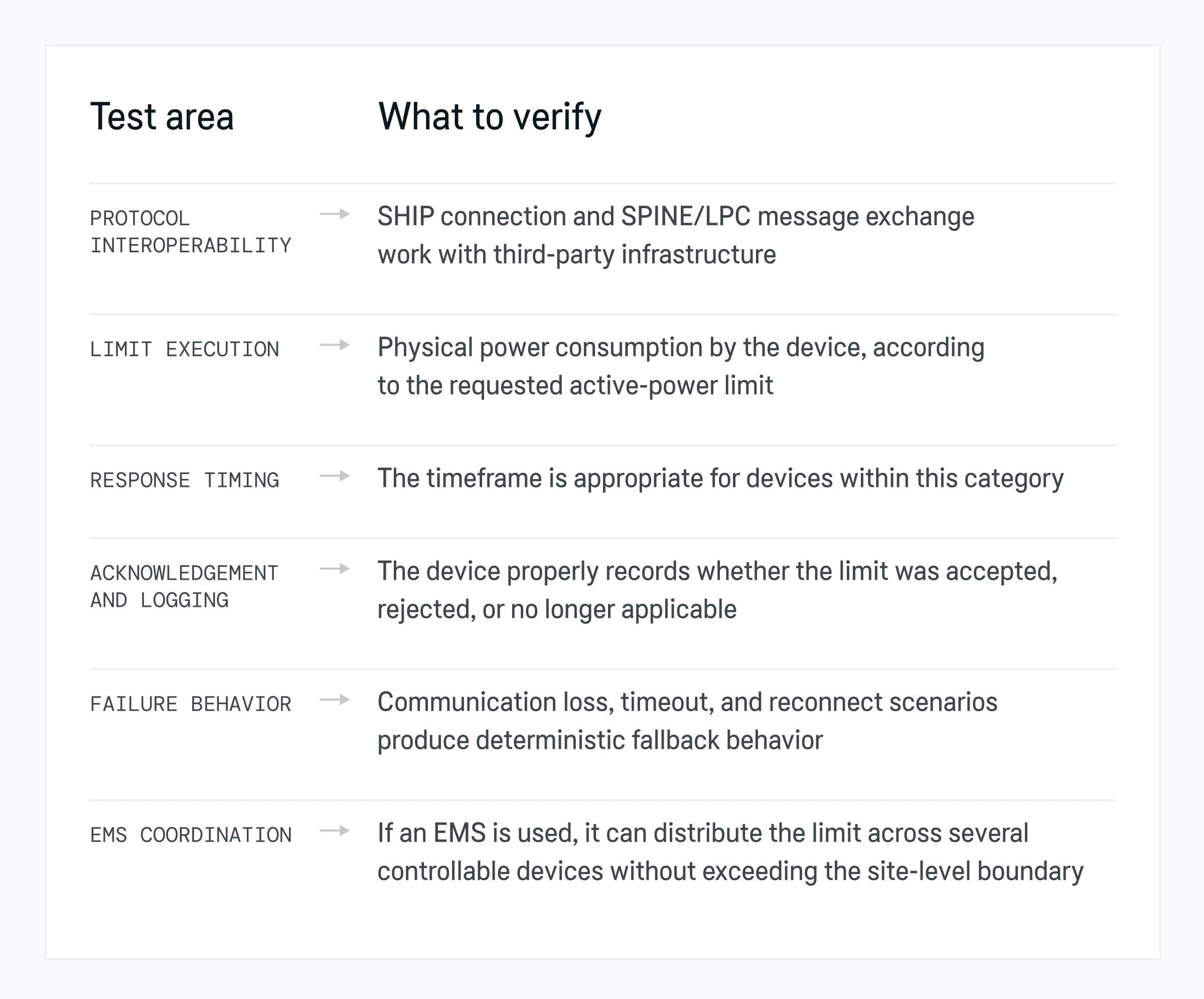
Lastly, all devices should be tested before being sent to the field to ensure they can reduce consumption correctly, respond within the expected timeframe, or handle communication errors predictably.
You should run two types of tests:
For that, OEMs need to test the full control chain: pairing, secure connection setup, command reception, acknowledgement, limit application, monitoring feedback, timeout behavior, and recovery when the limit is removed.
For an EV charging box, for example, the testing should prove that the LPC command was accepted and understood. It should then verify if the charging current was reduced or paused, and if the new charging state was communicated correctly.
Ideally, your qualification plan for the device should prove the following:
Channeling resources towards §14a readiness may not seem like the best capital allocation decision when it’s just one market at stake.
While Germany has been explicit about implementing LPC, other countries are moving in a similar direction of low-voltage congestion management.
Implementing EEBUS/LPC for Germany, thus, provides you with a scalable control architecture, reusable in other markets. Capabilities like support for controllable power limits, secure communication, telemetry, acknowledgement, failsafe logic, and OTA updateability can be advantageous for participation in other demand-response programs.
In that sense, §14a compliance becomes a stepping stone toward a broader product category: grid-interactive devices that can participate in regulated flexibility ecosystems across multiple markets.
§14a readiness is not a single protocol implementation or a compliance label. It is an engineering program that cuts across embedded software, communication interfaces, cybersecurity, installer workflows, and lifecycle support.
Sigma Software helps industrial OEMs implement all the necessary controls for participating in the German grid-side control process. We’ll work with you to determine the current device architecture, identify gaps in controllability, and define the implementation path for EEBUS, SHIP, SPINE, LPC, EMS integration, secure onboarding, OTA updates, and field diagnostics.
Contact us to schedule a readiness review of your product.

Sigma Software Group provides IT services to enterprises, software product houses, and startups. Working since 2002, we have build deep domain knowledge in AdTech, automotive, aviation, gaming industry, telecom, e-learning, FinTech, PropTech. We constantly work to enrich our expertise with machine learning, cybersecurity, AR/VR, IoT, and other technologies. Here we share insights into tech news, software engineering tips, business methods, and company life.
Linkedin profile

High-volume clinics lose significant revenue daily due to restrictive digital workflows. The healthcare and wellness sectors are expanding rapidly. Behind the s...

A Software Bill of Materials (SBOM) is becoming one of the most important documents in modern software development. Still, many organizations struggle to create...

As cloud sovereignty becomes a strategic priority across the EU, Sigma Software applies its deep expertise and extensive experience to contribute to the develop...